LH 2.2 to 2.4 swap:
This swap is remarkably straightforward, and should be doable on an LH 2.2
car, turbo or non. These instructions detail everything you need to do the
swap, with the exception of:
1. Cruise control. The later speedometers which contain the
road-speed sensor necessary to run LH 2.4 lack the road speed sensor necessary
to output to earlier cruise control systems. I have not yet investigated
what is necessary to fully power the earlier cruise control, or swap the cruise
control modules.
2. Air conditioning. Air conditioning should not be affected by
this swap, but wiring does change between different versions of LH. As my
project car has the A/C system removed, I have no way to verify whether or not
it does in fact work.
3. Shift-Up light: Earlier shift-up lights are powered
by vacuum switches in the engine bay. This circuit is left untouched but non-functional.
Later shift-up lights are powered by the LH ECU. The two circuits are NOT
compatible. Earlier systems provide +12v to turn on the shift up light,
while later systems provide ground. Obviously the two are not swappable
without more work than they're worth. If you really need your shift-up
light back, just wire the temperature sensor in the intake manifold (between
runners 1 & 2) to the 2-pin connector under the throttlebody. Or, just
remove the system (relay, switch, fuse).
NOTE: After the swap is complete, you will have up to three unused
connections:
1. The 2-pin speed sensor output to the cruise control (as above).
Zip tie it up behind the dashboard so it doesn't rattle around.
2. The 2 1-pin connectors near the LH ECU (turbos only) - LH 2.2 relies
on an overboost switch for fuel cutoff; LH 2.4 derives this information from the
AMM. You can remove the overboost switch and its wiring & vacuum hoses
after the swap to save weight. :)
3. The 1 2-pin connector under the throttlebody. This connector
bridges the shift-up light indicator temperature switch with the shift-up
chassis wiring. The LH 2.4 harness doesn't have provisions for the
external shift-up function.
These unused connections are exclusive of an unused yellow wire and unused
blue wire near the combined instruments cluster. Per below, the yellow
wire is the unused provision for the shift-up light, and the blue wire is the
unused provision for a cruise control road speed sensor.
IMPORTANT NOTE: This swap will require replacement of your
speedometer and odometer. In most states, this is considered tampering and
may be illegal or require special documentation or notification to future
buyers.
FINAL NOTE: This swap involves modifications to your car's fuel
injection system. This system is sensitive to physical trauma and
important to your car's proper operation. I have tried to ensure these
instructions are accurate, based on my own fuel injection swap and verified with
a second swap. You should only proceed down this road if you are
comfortable making fundamental changes to your car. At each step be sure
you do a basic sanity check to verify I haven't steered you wrong, and what
you're doing makes sense to you. If you have doubt or uncertainly, please
do not proceed. And, most importantly, please be fully aware that if you
proceed with this swap, you do so at your own risk!
Parts list (the easy way):
1. LH 2.4 ECU (1989-1990 900/S or 1989-1993 900T) with mounting bracket.
You can use LH harnesses from earlier LH 2.4 cars, but there may be subtle
differences (that you'll have to work out yourself). Don't forget the
mounting bracket - the LH 2.4 ECU will not mount on the earlier bracket.
2. Idle Control Valve (AIC) (1989-1990 900/S or 1989-1993 900T) with
mounting bracket from thermostat housing. Don't forget the mounting
bracket - the later AIC valves have a larger diameter.
3. Air Mass Meter (AMM) (1989-1990 900/S or 1989-1993 900T)
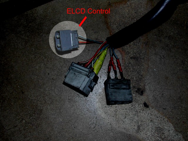
4. Evaporative Loss Control Device (ELCD/charcoal canister) (1989-1993
900/S/T)
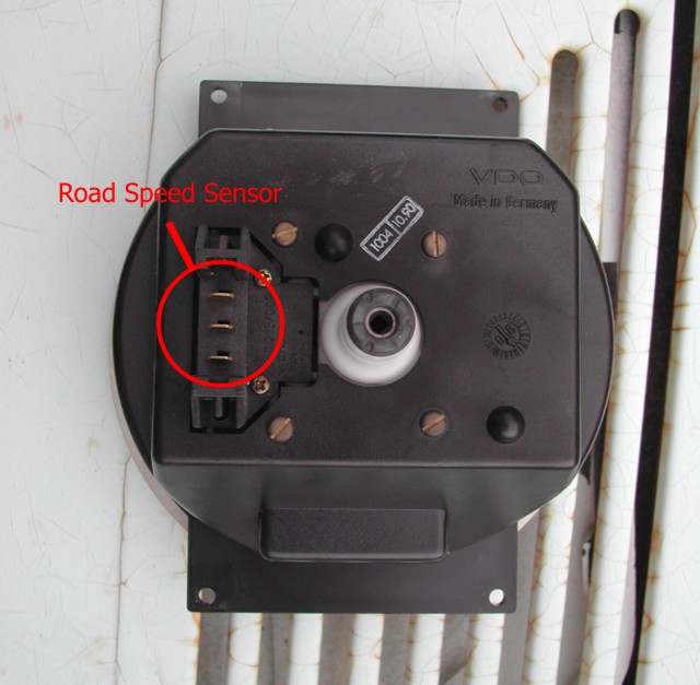
5. Speedometer (1989-1990 900/S/T)
(You can actually use any year speedometer as long as it includes the correct road
speed sensor. The correct road speed sensor will have a small circuit
board on the back; you can easily remove it from the speedometer by removing
the two retaining screws to verify you have the right one. If you grab
the speedo from a 1992+ 900, you'll be tempted to also grab the tachometer
and the combined gauge so that typefaces match. The tachometer,
speedometer, turbo gauge, and engine temperature gauge are
universal, but the fuel gauge is NOT. Later fuel gauges have a small
circuit to eliminate fuel level fluctuations ("anti slosh") on the gauge; without this circuit
you will fry the new fuel gauge!)
6. Speedometer cable (1989-1993 900/S/T)
Wiring components needed:
1. LH 2.4 wiring harness. Note: LH 2.2 wiring harnesses are
unique between turbo and non-, turbo harnesses do not have provisions for EZK
ignition. LH 2.4 harnesses are all the same and all have provisions for
EZK, even if they're unused.
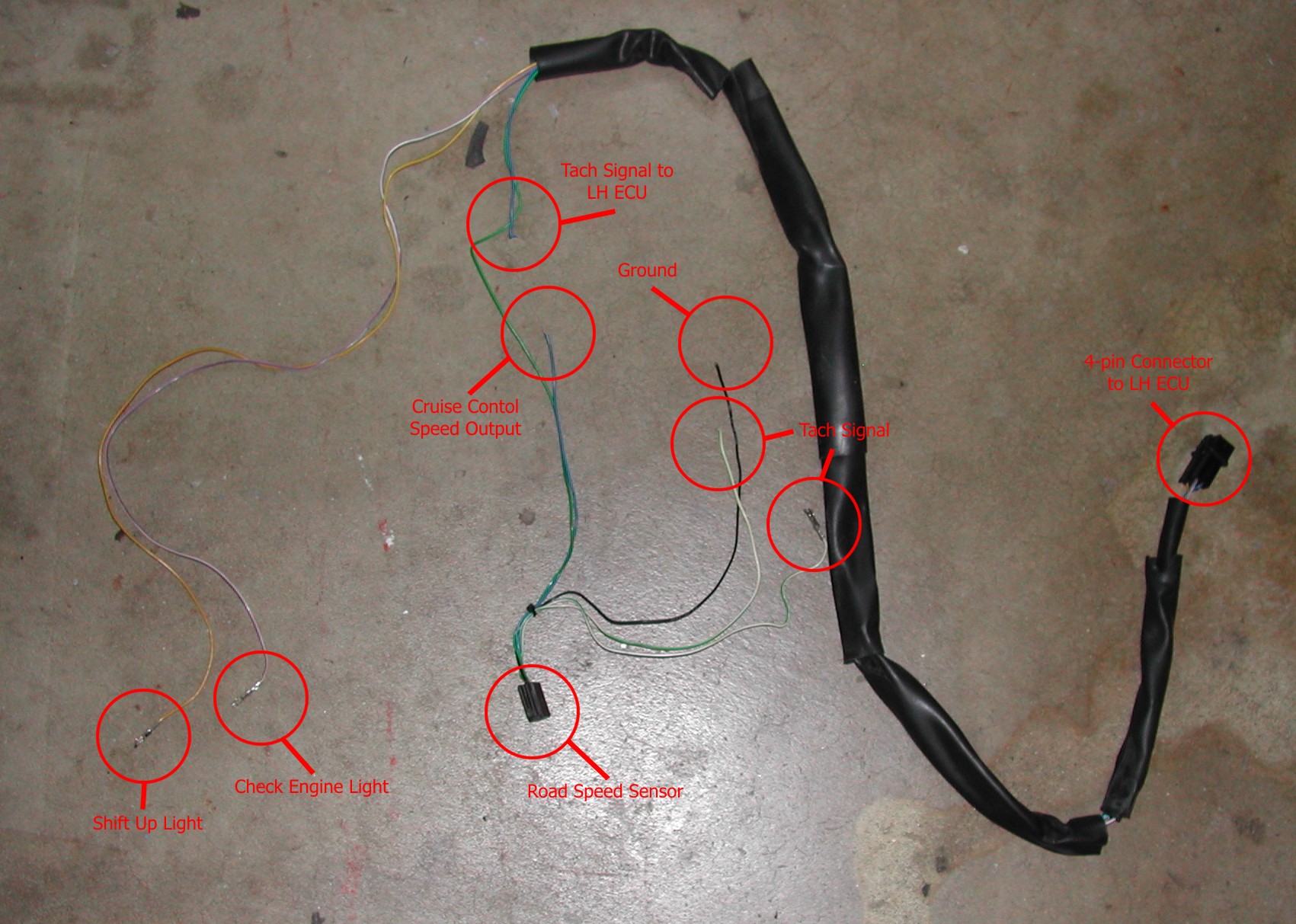
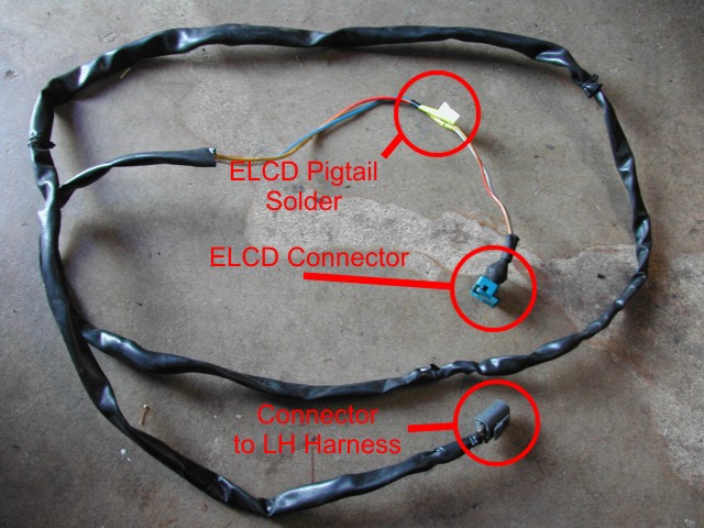
2. Pigtail from road speed sensor on the back of the speedometer.
(If possible, trace the green and yellow wire all the way back to the FI
ECU - it terminates in a 5-pin connector of which 4 are used. One green/white wire should be removed from the 14-pin connector on
the combined instruments cluster in
the donor car and *not* cut. The other three wires (blue, green/white,
black) may be cut. Leave at least 3-4" of extra wire. Below is
a sample of what that harness ideally should look like)
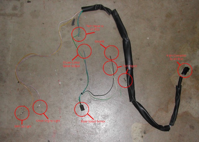
(Click image for a larger version)
3. Pigtail from ELCD
4. Male 2-pin plastic shroud
(You can grab this shroud from anywhere - from door lock motor wiring or
foglight wiring, for example. Just flip open the trap door and neatly
withdraw the existing wiring.)
5. Female 2-pin connector with 8' of wire
(You can grab this from anywhere. The connected 8' of wire is not explicitly
necessary, but it will simplify your wiring job. The real key here is
to have the female 2-pin connector and 8' of wire. Ensure your wire is
insulated - I suggest using scrap black insulation from another Saab.
You do not want grease, oil, and heat eating your wires!)
6. 5-pin (4 used) connector matching the 5-pin connector on the LH 2.4
wiring harness near the ECU. See item #2, road speed sensor, above.
Prep the car by removing old fuel injection components:
1. Unplug the battery
2. Remove the horizontal and vertical kick plates on the passenger
side, pull the carpeting away from the side of the car, exposing the ECU.
3. Remove the seats (to makes things easier), the lower dash pad, the
fascia, existing instrument cluster
4. Remove the screws holding the ECU to its mounting bracket and remove
the existing ECU
5. Remove the ECU mounting bracket
4. Remove the AIC (including bracket), AMM, ELCD. You may need to
remove the EZK or APC control unit to get the ELCD out.
6. Unbolt the p/s fluid reservoir and pull it away from the car as much
as possible - do NOT damage the lines or you will end up with a huge mess.
Remove the old fuel injection harness:
1. Starting at the AMM, disconnect the engine wiring harness from the
engine components, and cut/remove all the tiewraps securing it to the car.
Don't miss the 3-pin (non-turbos only) and 6-pin connector under the cabin air intake, the 1-pin
and 2-pin connectors for the O2 sensor, the 2-pin connector for the shift up
light temperature sender, and the lug at the power distribution
block. Leave it hanging over the passenger side fender.
2. Cut the tiewrap surrounding the boot that the harness passes through
the side panel into the cabin.
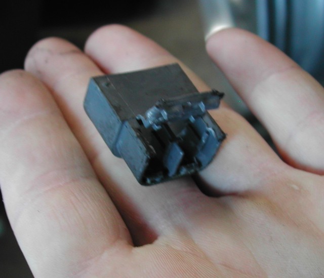
3. Unbolt the fuel injection relay block from the car.
4. Disconnect the 2-pin connector and the two 1-pin connectors (the
latter on turbos
only) and the 1-pin connector (automatics only) near the fuel injection relay block
5. Carefully pass through the wiring harness through the passenger side
panel (from inside to outside). It will fit. Remove the old wiring harness from the car.
Modify & Install the new fuel injection harness
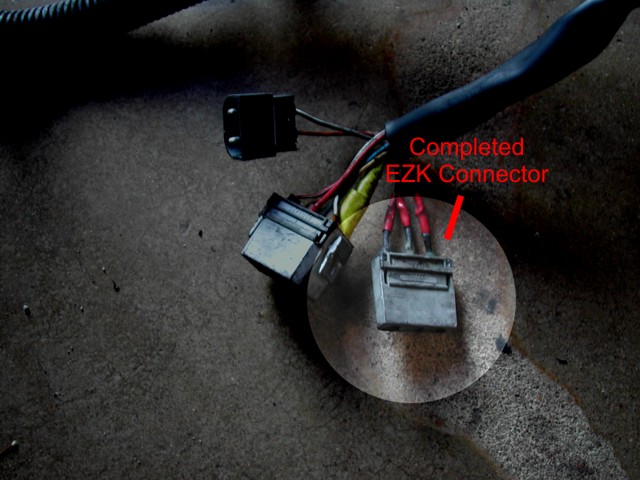
1. For non-turbos: Cut the 3-pin connector (with blue/red, grey,
and black wires) previously located under the cabin air intake on the old fuel
injection harness. Leave 3" or so to give adequate room for soldering.
Find the 6-pin connector on the new harness where Pins 1, 2, and 3 are blue/red,
grey, and black. Open the 6-pin connector and remove the pins. Grab
wires 1, 2, and 3 (leaving behind 4 (blue/red) and 5 (grey/white) and 6
(yellow/red)). DO NOT CONFUSE PIN 1 AND PIN 4 - the pins are labeled on
the connector itself. Cut the ends off the 3 wires, and solder those leads to the
matching leads on the 3-pin connector - black to black, etc. These leads
are for the EZK ignition system. Note: It is advisable to complete
this step even if you do not run EZK. Securing the ends in a connector
will help prevent shorts or other damage to the wiring & components
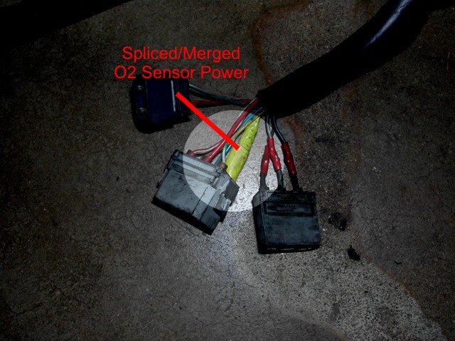
2. Grab the freed #4 (blue/red) pin from 6-pin #2 on the new harness, and cut the
end off. You must splice this wire onto the grey/red wire on the
6-pin #1 connector. This lead will provide power to the O2 sensor preheater.
If you like, you may solder an inline fuse though this is not strictly
necessary.
3. Clip the male 2-pin plastic shroud (from your parts inventory) onto the remaining two
wires (grey/white and yellow/red). These wires are for the electric purge valve on the ELCD.
4. Run the new LH 2.4 wiring harness along the engine bay. Pass the harness (AMM connector first)
through the hole in the passenger side fenderwall (be cautious of the power
steering lines) under the cabin air intake, and across the engine. Do not
twist or crimp the harness anymore than necessary to avoid breaking wires or
shearing insulation.
5. Using spare wire and a 2-pin female connector (from your parts
inventory), connect this 2-pin connector to the 2-pin connector prepared in step
#3. Run this wire along
the firewall and down the driver's side fender to the location of the ELCD. You can pass the wire
through the windshield wiper bracket and through the cutout in the fenderwall by the fusebox.
Solder or crimp the ELCD 2-pin pigtail onto the end of the wire. Secure
the wire in place.
6. Pass the FI ECU connector and relay block through the opening to the
passenger compartment (outside to inside).
7. Cut the end off the 2-pin connector on the car-side wiring by the
fuel injection relay block. The
connector will have a purple/white and a blue wire. Using the 5-pin
(4 used) connector and its pigtail, solder the matching purple/white and blue wires together,
and run the remaining green and yellow wires behind the dashboard to the
combined instruments cluster.
8. Install the new FI ECU bracket and relay block to the side of the
car.
9. Connect the FI ECU to the wiring harness and bolt the ECU to the
bracket.
10. Run the FI ECU diagnostic connector along the passenger-side sill
and under the back seat. Secure the 8-pin connector in an accessible
location. Depending on the year of the target car, you may be able to use
the original mounting bracket for this connector.
Install new fuel injection components:
1. Slide the ELCD into the retaining bracket on the driver's side
fender
2. Connect the AMM to the fresh air intake
3. Attach the new AIC mounting bracket to the thermostat housing and
install the AIC
4. Connect the new fuel injection harness to the newly-installed
components
Modify & Install the new combined instrument cluster:
1. Remove the combined instrument cluster, being careful not to damage
wires or the speedometer cable. The speedometer cable is secured to the
cluster using (normally) a Phillips-head screw.
2. Unbolt the tachometer and combo gauge from both combined instrument
clusters. On each cluster, lift the two gauges out together, to be sure
you do not damage the flexible circuit that links them together. Be
cautious not to damage the rheostat or clock adjustment knob. Remove the speedometer from each, and swap them.
Reassemble the original combined instrument cluster. If you are brave, you
may be able to adjust the mileage on the new odometer to match the old; doing so
requires some talent and you risk damaging the odometer. If you go this
route, you're on your own! Please note, in many states tampering with
the odometer is illegal, or requires special paperwork.
3. From underneath the car, disconnect the speedometer cable from the
transmission final drive. Carefully remove the speedometer cable from the
car. There should be two metal clips - one in the engine compartment, and
one inside the car - keeping the speedometer cable in place. Feed the cable into the engine bay, then remove from the top.
It's easiest if you remove the rubber grommet from the firewall rather than try
and feed the cable through it; you can remove the grommet once the cable is out
of the car. Install the new speedometer cable (installation is reverse of removal) and
connect it to the transmission final drive. Do not forget to clip the
cable into the metal clips - failure to do so may allow the cable to shift
during operating and hit the drive belts!
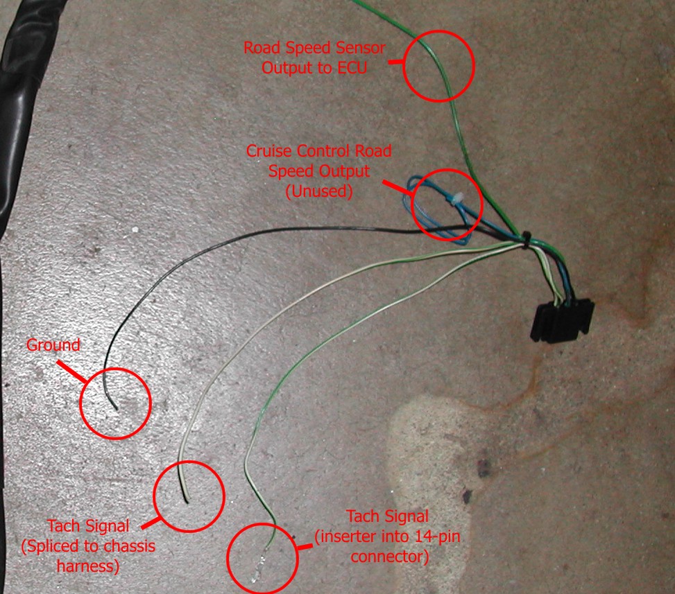
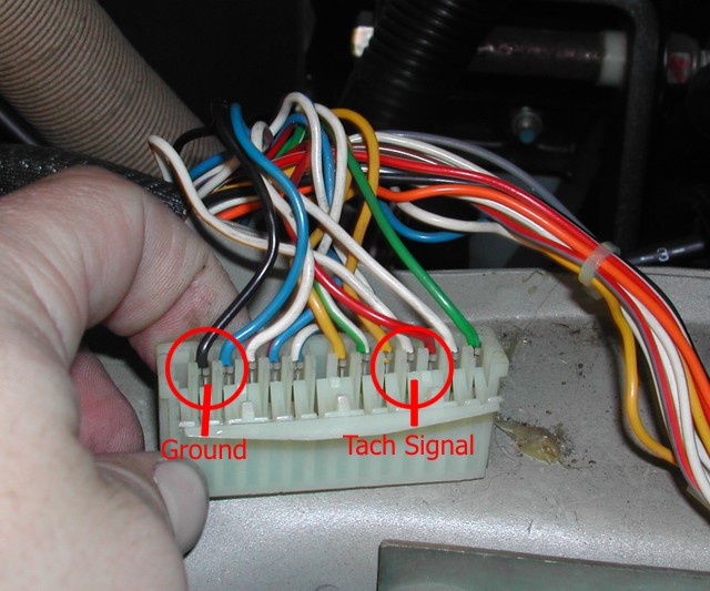
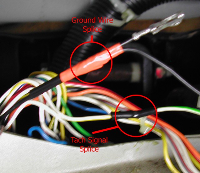
3. Remove (do not cut!) the tachometer signal wire from the left-hand
(gauge faces facing you) 14-pin connector in the dash area. This wire may
be blue, or may be green/white. I believe the Bentley manual is wrong
for several model years. This wire should be Pin 10 or Pin 11
(depending on year) on your
14-pin connector. Splice that wire onto the cut green/white wire on the road
speed sensor pigtail. Replace the wire removed from the 14-pin connector with the intact green/white
wire from the road speed sensor pigtail. Splice the black wire from the
road speed sensor pigtail onto a ground wire (always black, often pin #2) on the left-hand 14-pin connector.
The blue wire is output to the cruise control, and may be ignored. The
yellow wire is input for the shift-up light, and may ignored. Be sure
to insulate the ends of the unused wires to prevent shorting.
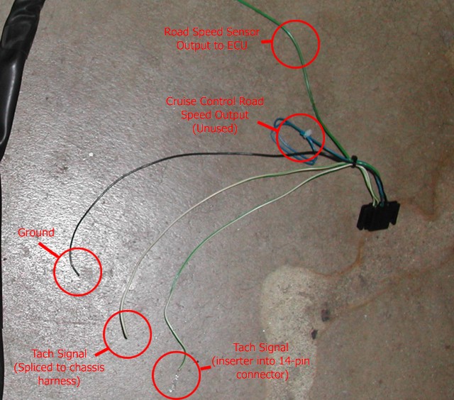
(Click image for a larger version)
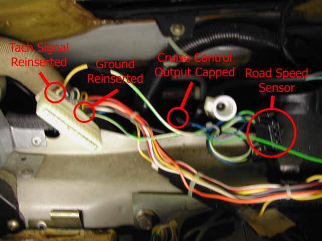
4. Connect the speedometer cable to the speedometer, connect the
newly-spliced road speed sensor, and reconnect the two 14-pin connectors.
Reinstall the combined instrument cluster.
5. Connect the 5-pin (4 used) connector at the passenger footwell to
the LH harness
6. Connect the 1-pin connector at the passenger footwell to the LH
harness (automatics only)
Verify all electronic connections:
1. Speedometer cable (at the speedometer & transmission)
2. Road-speed sensor (3-pin connector at the speedometer)
3. Combined instrument cluster interface to fuel injection ECU (5-pin
(4 used) connector at the passenger footwell)
4. Connect the 1-pin connector at the passenger footwell to the LH
harness (automatics only)
5. 6-pin connector at the cabin air intake (fuel injection interface to
chassis wiring)
6. 3-pin connector at the cabin air intake (fuel injection interface to
EZK
ignition system) (non-turbo) only
7. 1-pin and 2-pin connector at the cabin air intake (O2 sensor output
and preheater circuit)
8. Lug at power distribution block (fuel injection main power)
9. Engine sensors and components (AIC, AMM, injectors, coolant
temperature (NTC) sensor, air conditioning compressor and temperature switch)
Put your car back together! :D